

Planning a roofing welder generator setup is usually the last thing a buyer thinks about and the first thing that causes trouble on site. Both of the automatic roofing welders we supply — the Weldy Roof40 and the Weissenberg RWP1 — run on a 230 V nominal supply and are high-power electrical loads. Whether that power arrives cleanly, from a building supply, a temporary site supply or a generator, decides how the machine behaves at the seam. This guide covers what the machines are rated to draw, how to check the supply you intend to use, what a generator has to deliver, and what an extension cord does to the power that reaches the tool.
None of this is a reason to avoid these machines. Roof work happens where the roof is, which is often far from a convenient supply. It is a reason to settle the supply question before delivery rather than on the first morning of the job.
Why the Supply Is Part of the Welding Setup
Automatic roofing welders are high-power electrical loads. The generator, circuit and extension cord should be sized from the machine's rated input rather than from an assumed lower average consumption. Actual power demand varies as the heating control responds to the welding conditions.
The work is also different from a hand tool used in short bursts. One field seam can be 20 or 30 metres of steady travel at walking pace, so the load is a working condition that lasts rather than a momentary one, and the machine is heating throughout the run. The seam itself is formed by heat and pressure delivered at a steady travel speed.
The membrane sheet is factory-produced; the seams between sheets are created on site. A seam is formed on the roof, by an operator, at a temperature that is affected by sun, wind and substrate. Power delivery is one of the conditions in that setup, which is why it is worth treating as part of the welding setup rather than as an electrical detail that somebody else will deal with.
What a Roofing Welder Actually Draws
Start from the rating plate rather than from an assumption. These are the two automatic machines we supply:
| Model | Supply voltage | Rated input | Temperature range | Travel speed | Seam width | Net weight |
|---|---|---|---|---|---|---|
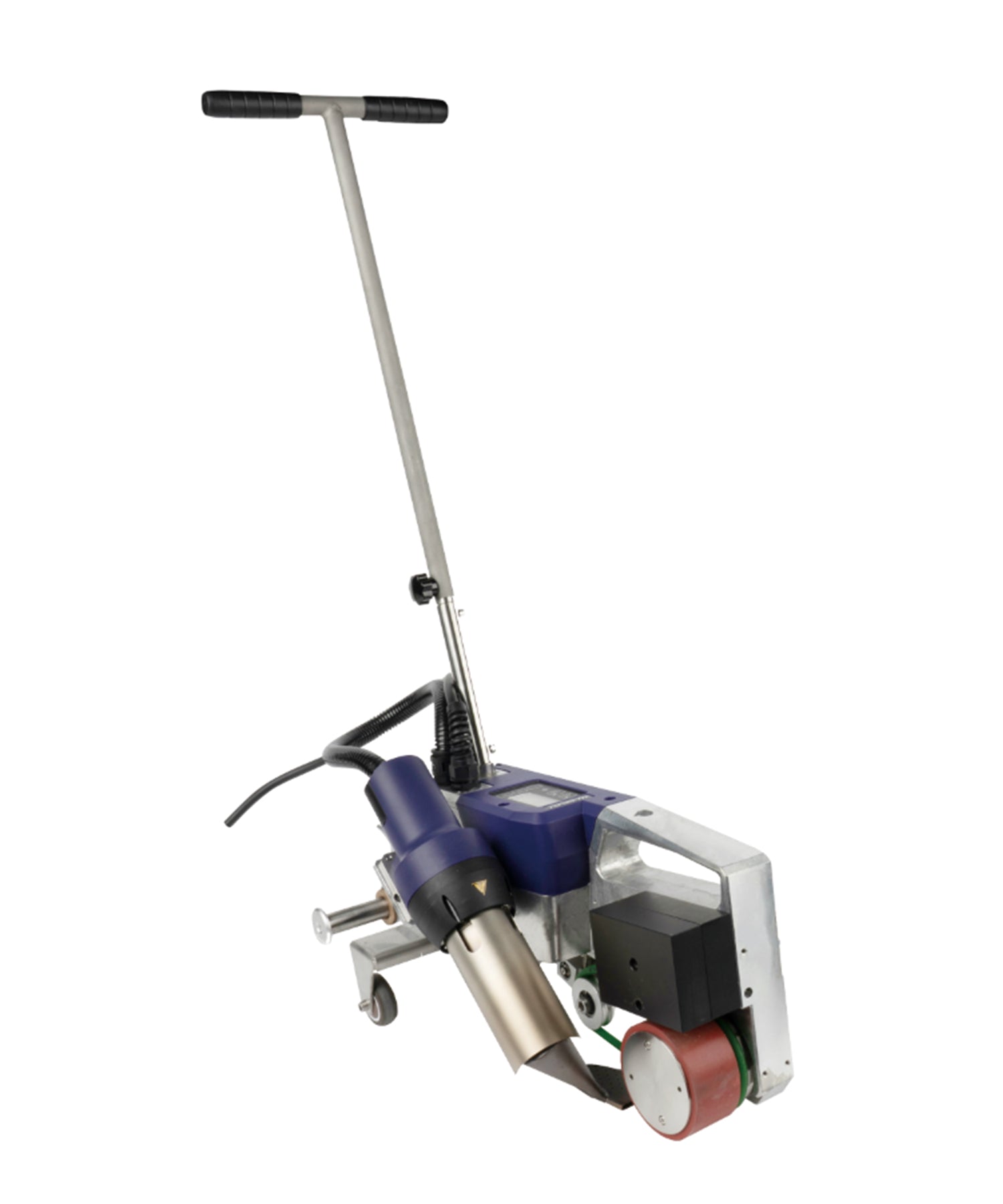
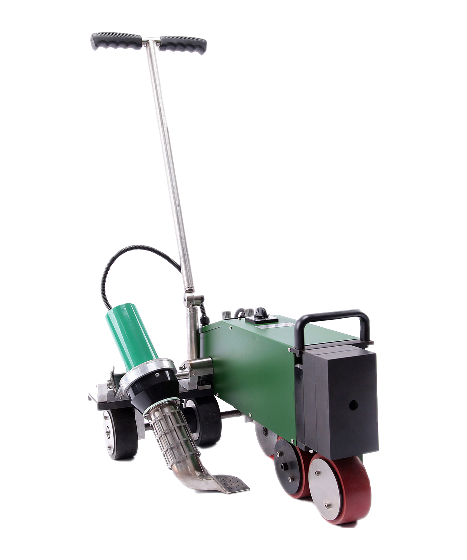
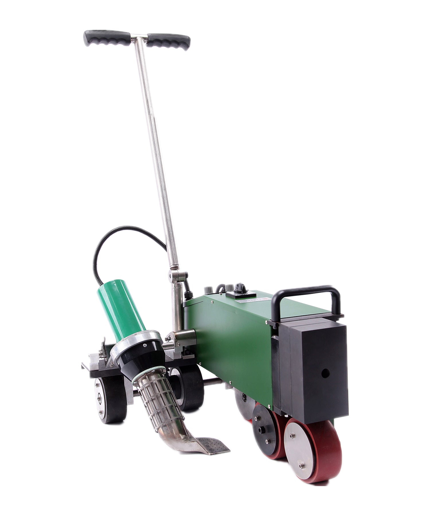
| Weldy Roof40 | 230 V | 3,450 W | 100 – 600 °C | 1 – 10 m/min | 40 mm | 15.5 kg |
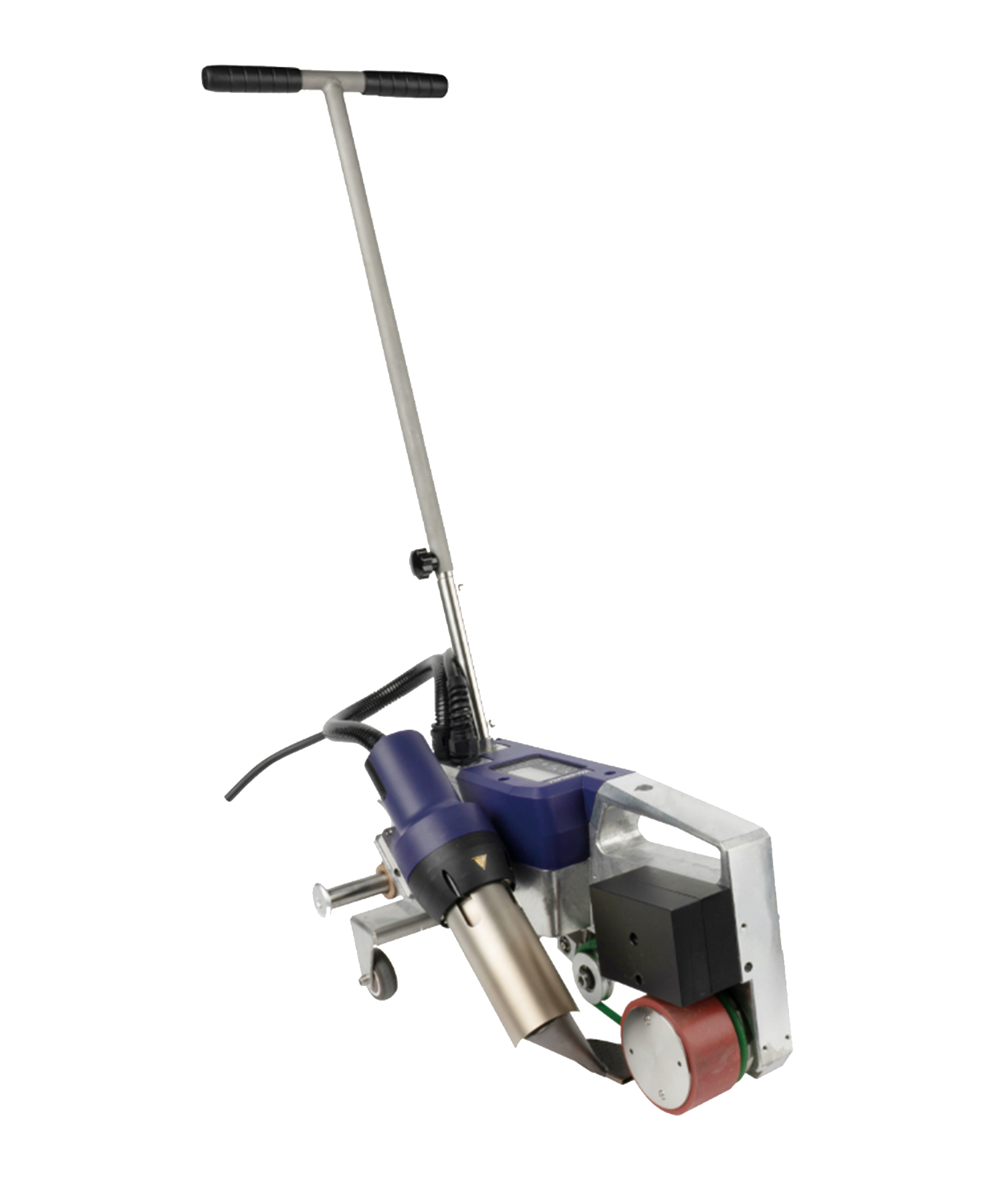
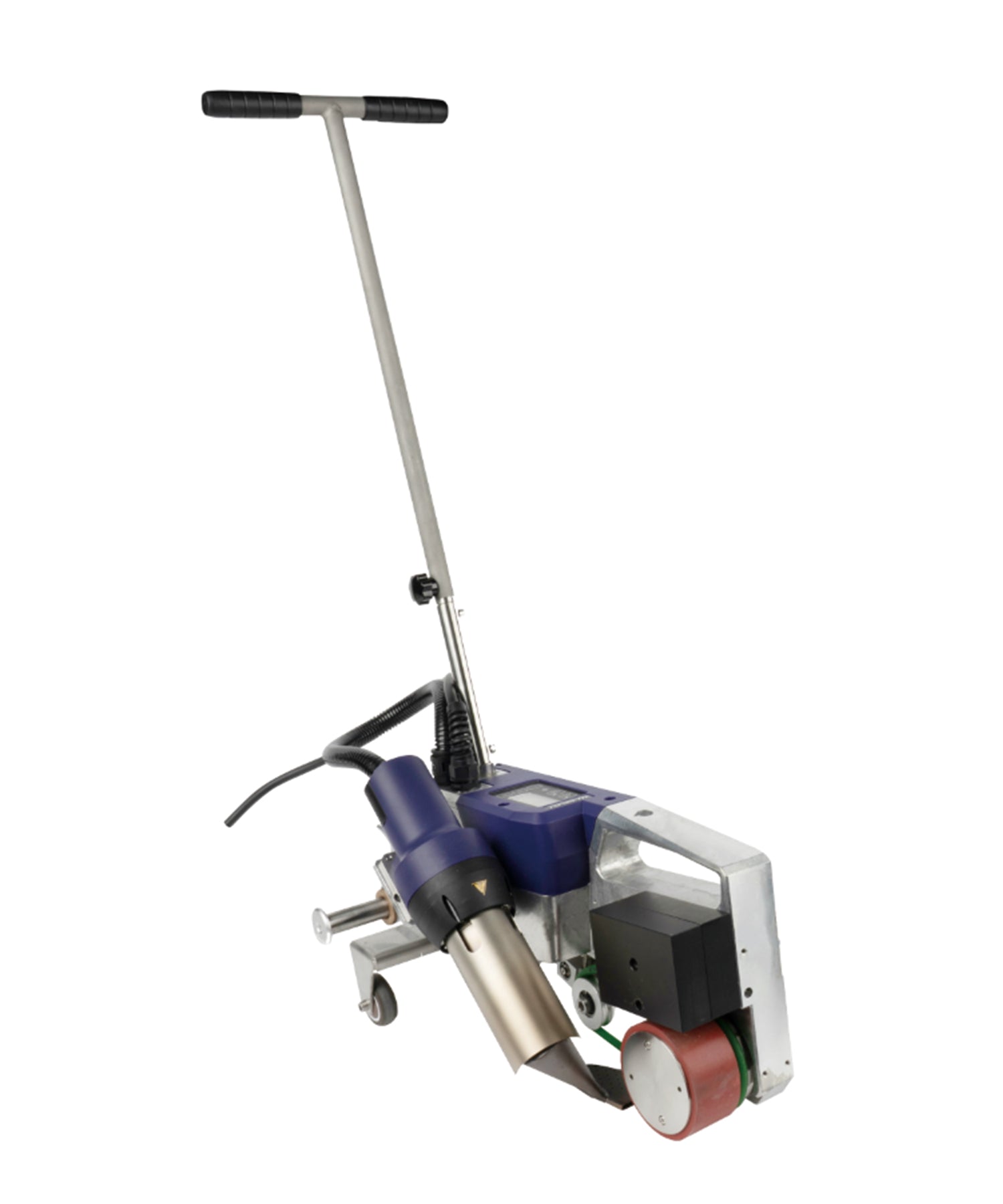
| Weissenberg RWP1 | 230 V | 4,200 W | 50 – 620 °C | 1 – 10 m/min | 40 mm | 38 kg |
Compliance note: Weldy article 159.522 is currently listed by the manufacturer as “No CE – no use in Europe.” Buyers in Europe should confirm the appropriate compliant model or variant before ordering.
At a nominal 230 V supply, a 3,450 W rated input corresponds to a reference current of about 15 A, and 4,200 W to about 18.3 A. These are simple P ÷ V references taken from the rating plate, not circuit-sizing values. What a particular outlet, generator or cord can actually deliver is a separate question, and it is one for a qualified electrician working to the electrical requirements that apply where you are. A machine of this class takes a large share of a site supply on its own, so what else is connected to the same supply matters, and a temporary site supply needs to be assessed on the same basis as a permanent one.
The versions of both machines supplied by us are 230 V. If the site you plan to work on does not provide a 230 V nominal supply, tell us before you order and we will confirm what is available for your market.
230 V Nominal: Check What Your Site Provides
The Roof40 and the RWP1 are built for a 230 V nominal supply. In Europe, the UK, Australia and many other markets that is the general-purpose supply. In North America, general-purpose outlets are commonly 120 V, while workshops, commercial roofs and industrial sites may also have 208 V or 240 V circuits. Do not assume the two are interchangeable: the nominal voltages differ, and the wiring arrangement and plug differ as well. If you intend to run either machine from a North American 208 V or 240 V service, confirm the compatibility with us before ordering rather than assuming it will suit your supply. Check the actual outlet and supply you intend to use.
The Roof40 and RWP1 versions discussed in this guide are 230 V machines. Do not connect a 230 V unit directly to a 120 V supply. Other voltage variants may exist for some product families, so always confirm the exact article number and rating plate before ordering. A plug adapter does not change that: it changes the shape of the pins, not the supply voltage. A 230 V unit is not rated for direct operation from a 120 V supply and may not operate correctly. Do not use it this way.
Choose the voltage version that matches the intended site supply rather than relying on a plug adapter or improvised voltage conversion. Tell us the country the machine is going to and the version and plug are matched to that destination at the time of ordering.
Running a Roofing Welder from a Generator
On many projects there is no building supply within reach of the roof, and a generator is the working answer. For a roofing welder generator setup, sizing comes down to a handful of things that are quick to check and expensive to get wrong.
- Continuous output, not the peak figure. Generators are usually described by more than one number. For a tool that heats through a long run, the figure that matters is the output the generator can carry continuously, not the short-term rating quoted for motor starting.
- The machine's rated input is the starting point. The rating plate gives the load the generator has to carry: 3,450 W for the Roof40, 4,200 W for the RWP1. That figure comes before anything else on site is added to it.
- Everything else on the same generator. Site lighting, chargers, compressors and the hand gun used for detail work all draw from the same output, and they are running while the welder is running.
- The output voltage and frequency. The machine is rated for a 230 V supply at the frequency shown on its rating plate. Check that the generator's output matches what the machine is rated for instead of treating any 230 V source as equivalent.
- Connection and earthing. How a generator is connected and earthed on site is governed by the requirements that apply where you work.
Generator Sizing Framework
There is no single generator figure that is correct everywhere, but the starting point is not a mystery. It is the machine's rated input, and the principle that the generator has to carry it together with every load that runs at the same time:
| Machine | Rated input | Approx. rated-current reference at 230 V | Generator starting point |
|---|---|---|---|
| Weldy Roof40 | 3,450 W | ~15 A | Generator continuous output must cover the machine's rated load plus all simultaneous loads |
| Weissenberg RWP1 | 4,200 W | ~18.3 A | Same principle; final generator rating must account for other loads and generator/site conditions |
These current figures are simple P ÷ V references, not circuit-sizing values. Use the machine rating plate and have the final generator, circuit and cord selection confirmed for the site.
There is no single minimum generator rating that applies to every site. The required generator capacity depends on the welder's rated input, simultaneous loads, the generator's continuous-output characteristics, site conditions and the applicable electrical requirements. Give the generator supplier or a qualified electrician the machine's rating plate details together with the list of what else will be running, and have the sizing confirmed before the equipment is mobilised.
One point that catches crews out: a generator that is comfortable with a hand gun may not cover an automatic welder. A 1,600 W hand gun and a 4,200 W roofing machine are in different classes, so a generator sized around the smaller tool has to be checked against the welder's rated input before it is relied on.
Generator Headroom
Start with the roofing welder's rated input, then add every load that will operate at the same time. The generator must provide sufficient continuous output at the required voltage and frequency. Any additional headroom, derating for site conditions or allowance for motor starting should follow the generator manufacturer's sizing guidance and the machine's actual electrical characteristics rather than a fixed multiplier.
If the generator is rated in kVA rather than kW, do not treat the two figures as interchangeable. Check the manufacturer's continuous kW output and rated power factor when confirming capacity.
The Two Machines Do Not Share the Same Supply Assumption
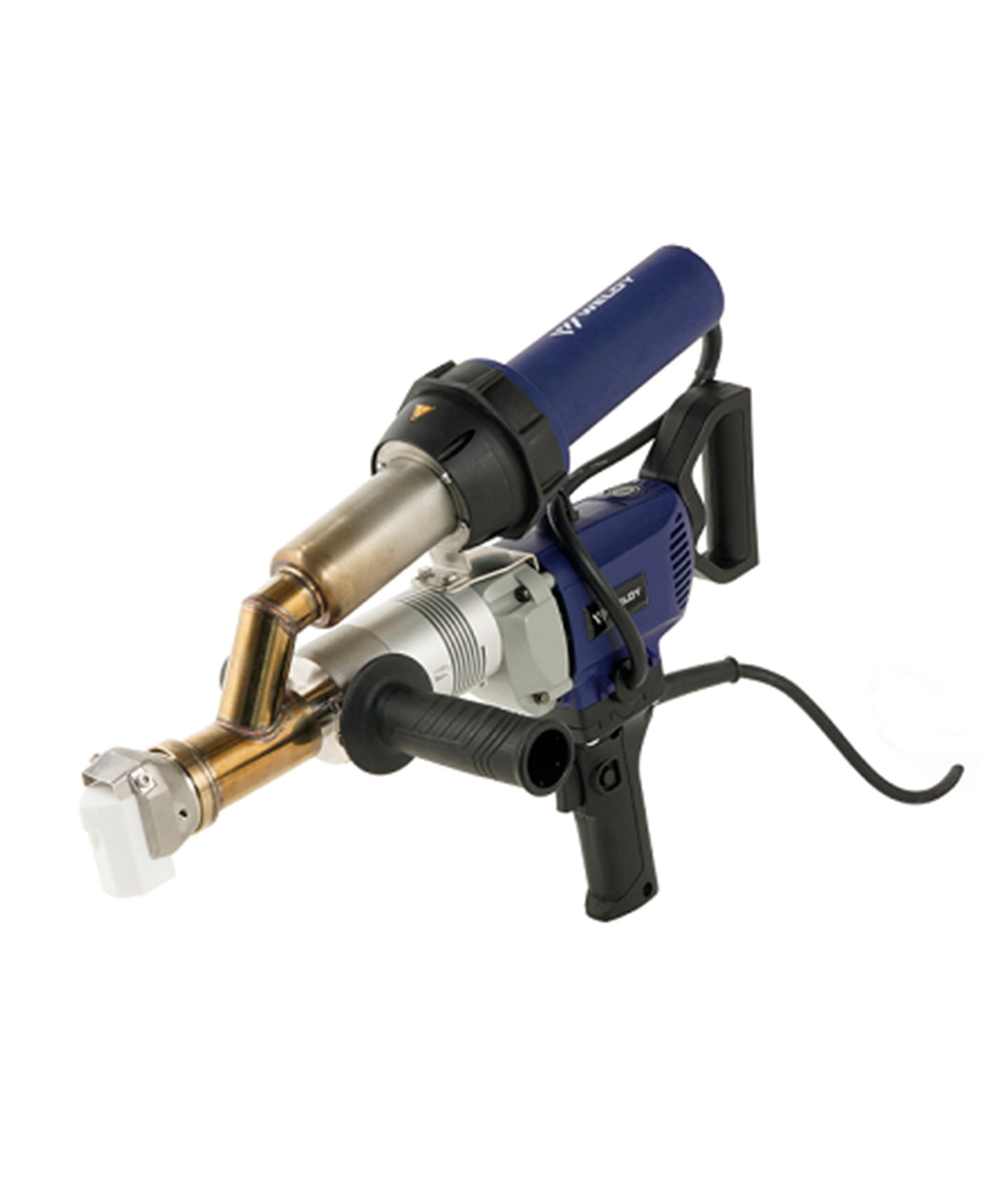
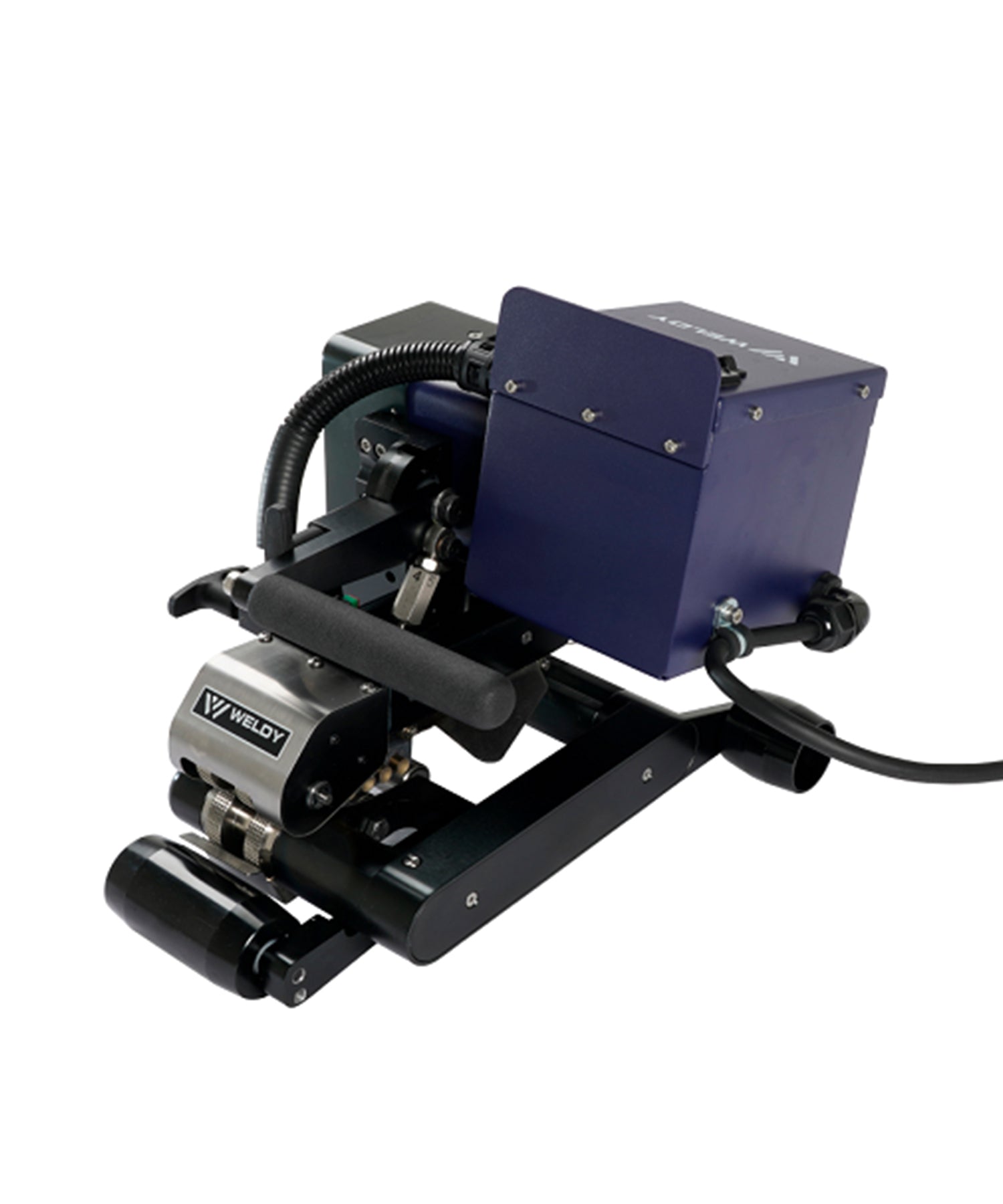
There is a difference between the two machines that is easy to miss on a job sheet. The Roof40 is listed by Weldy with a CEE 16 A connection. The RWP1's rated input corresponds to a reference current of about 18.3 A at 230 V, which sits above what a 16 A connection is rated to carry.
Do not assume that a supply, connector, cord or generator set up around the Roof40 will suit the RWP1. If the crew runs both machines, the power arrangement has to suit the larger of the two, and what the installation can actually carry still has to be confirmed for the machine that will run from it.

Extension Cords: Length, Conductor Size and Voltage Drop
Where a supply exists but is not close to the work, a cord is the usual answer — and one of the usual reasons a machine behaves differently than it did at set-up.
Every metre of cord has resistance. Over a long run, and with a conductor that is too light for the current, that resistance takes a share of the supply before it reaches the machine. Excessive voltage drop reduces the heating power available to the tool and can slow temperature recovery or prevent it from maintaining the required working temperature under load. The machine is still set to the values the trial weld confirmed; what has changed is the power arriving at the heating element.
How to Work Out Whether a Cord Suits the Load
There is no universal table that answers this, because the same cord behaves differently at different supply voltages and in different conditions. What there is, is an arithmetic that uses three numbers you already have. Work through it in this order:
- The current the cord has to carry. Take it from the machine's rated input: 3,450 W ÷ 230 V ≈ 15 A for the Roof40, 4,200 W ÷ 230 V ≈ 18.3 A for the RWP1. Base the cord calculation on the load actually carried by that cord. For these high-power roofing welders, use a dedicated cord and supply path rather than sharing the extension cord with other tools.
- The voltage drop along the run. For a single-phase 230 V circuit, the approximate drop is ΔU ≈ (2 × L × I × ρ) ÷ A, where L is the one-way length of the run in metres, I is the current from step 1, ρ is the resistivity of the conductor (about 0.0175 Ω·mm²/m for copper) and A is the conductor cross-section in mm². The factor of 2 accounts for the current going out and coming back. Express the result as a percentage of the 230 V supply to compare it with the limit you are working to.
- The limit it has to meet, and the cord's own rating. The acceptable drop and the conductor size that delivers it are set by the electrical requirements that apply where you work. Separately, the cord, connectors and plugs must be rated to carry that current in the ambient conditions on the roof — a cord can be electrically long enough in principle and still be the wrong cable for the site.
The arithmetic tells you how the three numbers move together, which is what makes it useful on site. Drop is proportional to the current and to the length, so doubling the run doubles the drop. Voltage drop is inversely proportional to conductor cross-sectional area, so doubling the conductor area approximately halves the calculated resistive voltage drop. Conductor resistance also rises as the cable warms up, so treat the result as a planning figure rather than a measured value. What it does not do is override the installation requirements: select the cord with a qualified electrician against those requirements before the work starts.
- Length and conductor size belong together. A cord that is suitable at 10 m can be unsuitable at 40 m. Both figures matter at once, and the combination that suits the load is a question for a qualified electrician rather than a general rule.
- The cord has to be rated for the load and the site. Cords, connectors and plugs used on site must be suitable for the duty and the environment. Damaged, taped or mismatched connectors are a fault waiting to happen.
- Do not leave the cord coiled. A coiled cord under a heavy load cannot shed heat. Run it out.
- Keep the number of joints down. Each additional connector is another point of resistance and another thing to check.
- Run the machine on its own cord. Sharing a cord puts two loads on the same supply path.
If a seam that was set up correctly starts to behave differently once the machine has moved further from the supply, the cord is one of the things to check — alongside travel speed, roller pressure and the condition of the membrane surface. Have the cord you intend to use checked by a qualified electrician against the electrical requirements that apply locally rather than deciding on site.

When the Supply Is Limiting the Weld
Supply problems rarely announce themselves as electrical faults. They show up in the seam, where they look like several other things. Work through the possibilities rather than assuming a cause:
| What you see | Possible causes to verify |
|---|---|
| Temperature does not recover after the machine stops and starts again | Heat input and travel speed for the membrane; how long the machine pauses; the power available at that point on the supply path |
| The machine will not hold the working temperature on a long run | Cord length and conductor size on the run; total load on the supply; ambient conditions on the roof; the temperature setting itself |
| Supply protection operates during a seam | What else is connected to the same supply; the rating of the installation; the condition of the connectors and the cord |
| Seams that look closed but have not developed adequate fusion between the membrane layers | Heat input; travel speed; roller pressure and consolidation; contamination, moisture or weathering on the overlap; an unsuitable setup |
| Behaviour changes between two roofs or between morning and afternoon | Weather and substrate; supply path and cord run; anything changed in the machine setup since the trial weld |
In each case, work through the process variables first — heat input, travel speed, contact pressure and the condition of the surfaces — and treat the supply as a separate check rather than the assumed cause. A trial weld on a sample of the membrane you are installing is what establishes the setup, and it is also the reference that tells you whether the machine has changed. If the machine welds correctly close to the supply and behaves differently at the far end of a long cord, that difference is information about the supply path.
Seam quality is checked according to the specified seam-check procedure for the roofing system. A field seam check does not replace the trial weld used to establish the welding setup.
Five Things to Confirm Before You Order
- The supply at the site you will actually work on. Confirm the nominal voltage, the plug arrangement and whether the machine will be run from a building supply, a temporary supply or a generator.
- Who will sign off the installation. Have the intended supply and any cord run checked by a qualified electrician against the electrical requirements that apply where you work.
- If a generator is involved: its continuous output, everything else that will run on it, the output voltage and frequency, and how it will be connected and earthed.
- The cord plan. Length, conductor size and connectors decided together and checked before mobilisation, not chosen on the roof.
- The welding setup itself. Check the practice against the membrane manufacturer's welding instructions and any published starting guidance for temperature, travel speed, roller, overlap and sequence. Final settings should be confirmed by the trial weld.
Answer these five and the power side of the project stops being a variable. It is also worth having the answers before you order rather than after delivery, because the supply often decides which version of a machine is the right one for the site.
Power for the Detail Work Too
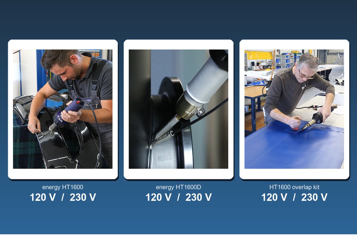
An automatic welder covers the field seams; the details around pipes, corners and terminations are usually welded by hand. The power question follows the tool. The Weldy energy HT1600D and energy HT1600 hand guns draw 1,600 W and are supplied as separate 120 V and 230 V versions, so the version you order follows the supply you will work from. On a 230 V site, whether the hand gun and the welder can run from the same supply at the same time depends on what that installation is rated to carry and what else is connected to it.
The RWP1 uses closed-loop control to maintain the set temperature and travel speed, helping keep the welding parameters stable during operation; the Roof40 is specified as capable of close-to-the-edge welding up to 100 mm. For hand-welded roofing details, a 40 × 2 mm wide-slot nozzle and a 40 mm silicone pressure roller are commonly used with compatible hot-air hand tools, and nozzle and roller selection for detail work is set out in our nozzle guide. The required detail seam width should still follow the roofing membrane manufacturer's procedure.

Roofing Welders and Accessories at Weissenberg Store
Both machines are available through our roofing welder collection, alongside the hot air guns and accessories used for detail work. The RWP1 is manufactured by Weissenberg with 1-year warranty and lifetime technical support. As an official Weldy distributor we also supply the Roof40, and our technical team is happy to look at your supply details against the machine before you order — send us the supply voltage at the site, whether a generator is involved, and how far the work is from the outlet, and we will tell you what the machine needs.
If power delivery is the question you are trying to settle, ask us. It is easier to answer before the equipment is shipped than after it has been carried onto a roof.





Leave a comment
This site is protected by hCaptcha and the hCaptcha Privacy Policy and Terms of Service apply.